The Dark Tower
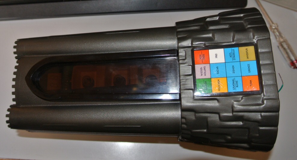
The Dark Tower boardgame was one of the first electronic boardgames. It was sold in ~1982/83. For some reason it is called 'Atlantis' in germany. Because of a dispute it was soon taken off the market. So (it is said that) there were not that many sold. It became a collectors item and is traded between 70-250 Euros. Also because it's so retro. I always wanted to know what they built there, but didn't find images of someone taking it apart. So I got one, didn't turn it on, but took it apart. This one was sold as defective. I think it works well. There seems to be a possible glitch during power up which might be interpreted as fault. If this happends the leds don't show what they are supposed to show. Also the motor will not work in this state. Disconnecting the power for a few seconds fixes this. Sometimes it needs a few tries. It works when the motor does a tiny jump shortly after power connection. Maybe this is due to the power system. It uses the 3V from the two batteris, und also generates 9V from it. - tower
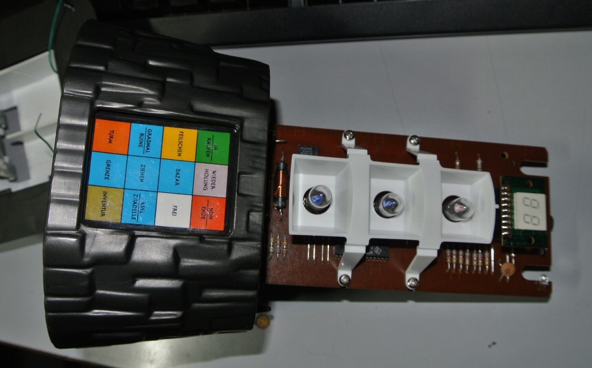
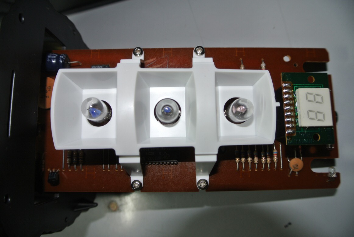
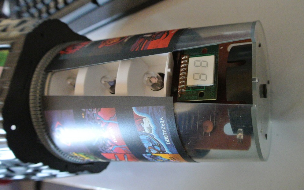
Without the top lid. The top lid is held in place by one screw, hidden under a removable piece of plastic. The cylinder turns into a position and one of the 3 lights illuminates a symbol with text, which tells the player what just happened to them. Also a corresponding sound is played, for everyone to hear. So they can laugh if he is about to lose a battle.
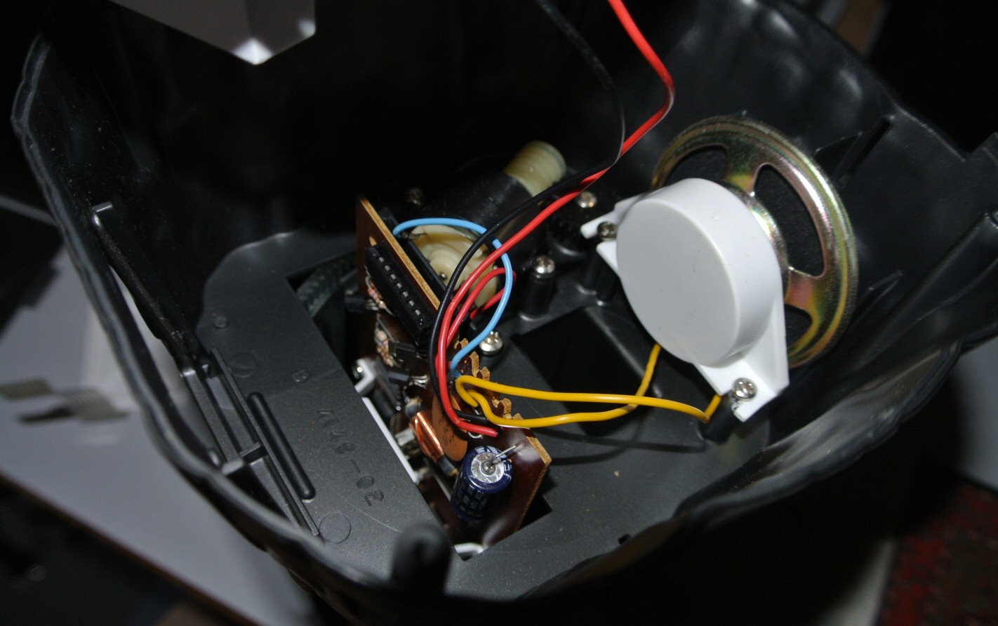
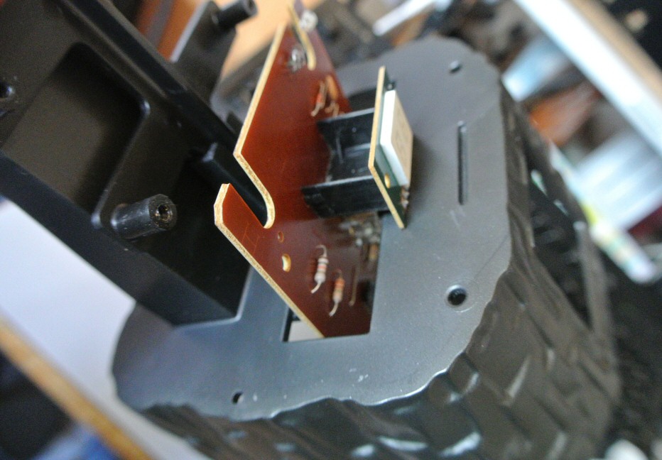
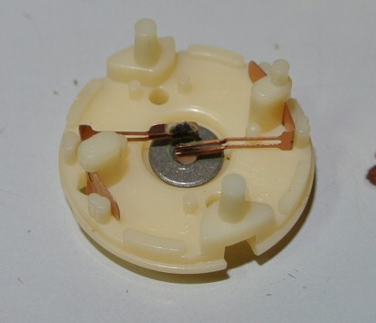
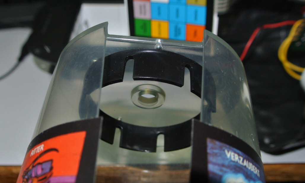
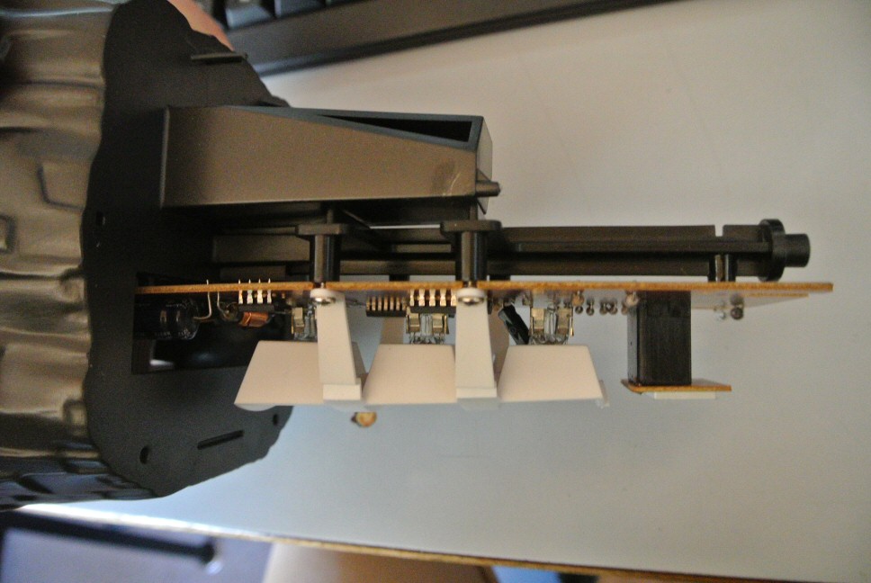
Without the turnable cylinder. Photo sensor to the right. These 4 screws keep the circuit board and the white light blocker in place. Side view. Encoder wheel for the photo sensor. It just has one larger opening (90° to the right), which means that the open side is facing the user.
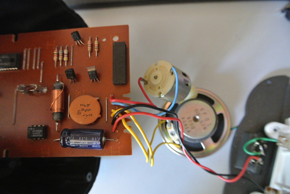
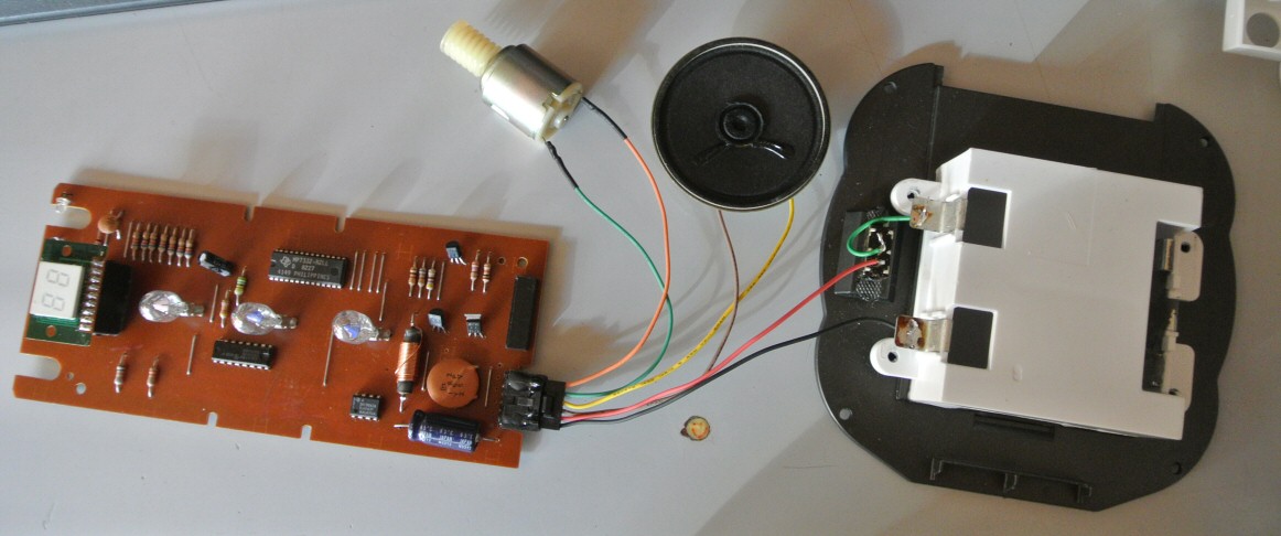
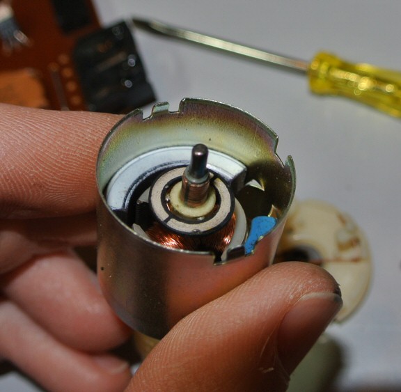
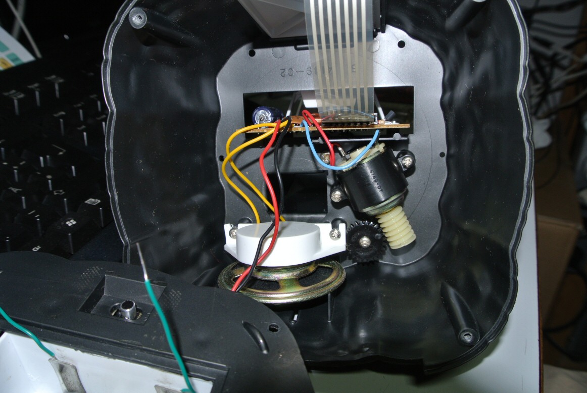
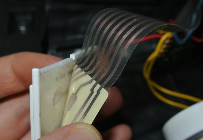
Access from below. Keypad at the top. Keypad is easily unpluggable. It is held in place just by the bottom lid. But speaker, motor and battery holder are soldered. Which means that we can pull the board out to some degree but we cannot remove it. That's why I decided to solder in a pluggable connector. Once and for all. German keypad. A quick look into the keypad. Simple 3 layer technique. The motor did work but not very powerful. So I opened it up and cleaned off dirt ans greasy residue.
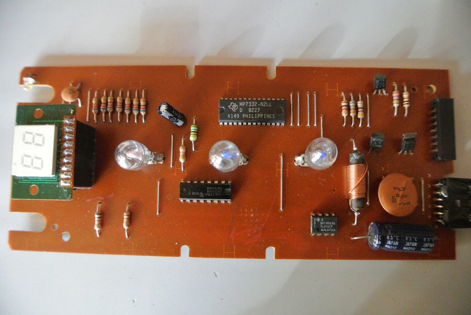
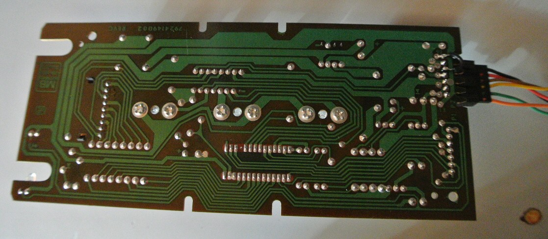

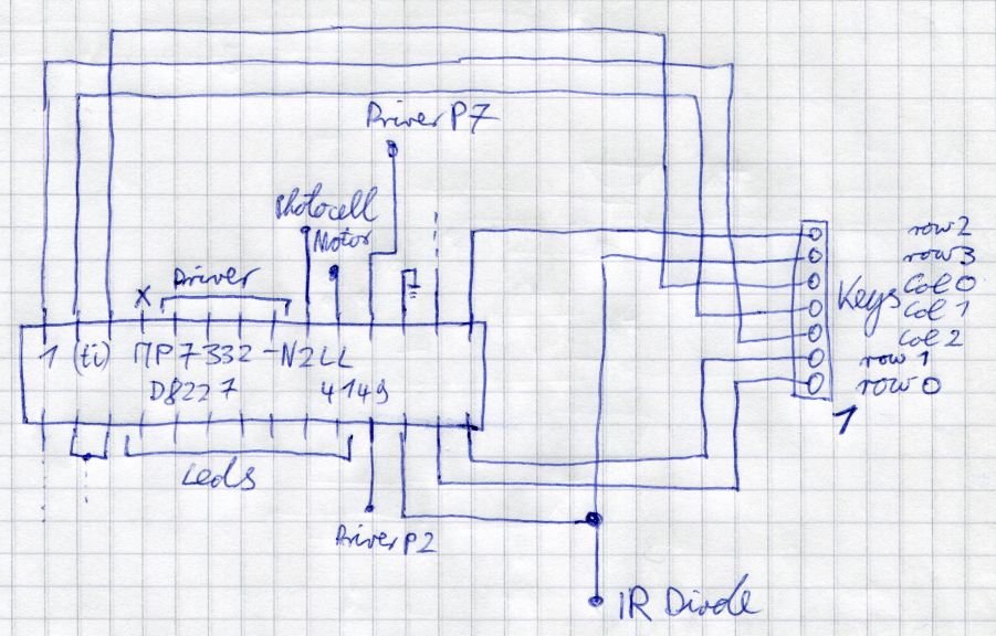
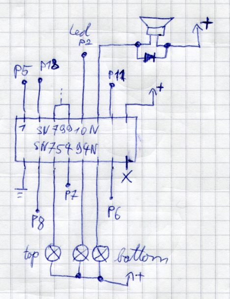
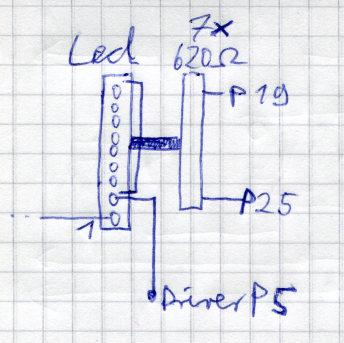
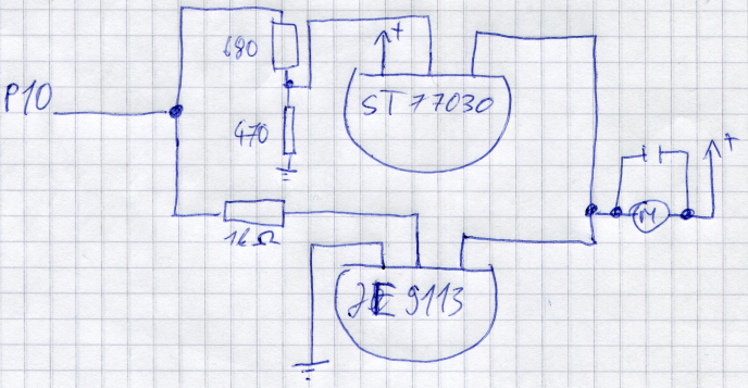
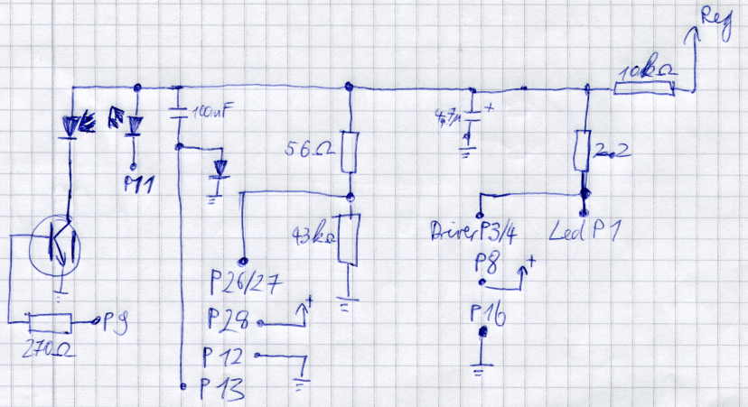
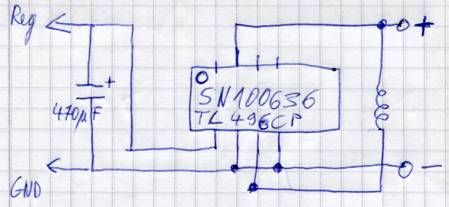
Circuit diagrams Px means pin x at the main IC. Otherwise they are named like 'led Px' or 'driver Px'. IC Pin 1 is at top left, because I followed the traces viewing the board from bottom side. + and - are the 2*1,5V battery connectors. The main IC seems to be something custom made. I found barely anything on the internet about it. Step up SN100636 TL496CP: The step up generates 9V form 3V. I called it 'Reg' for regulated. For ground I used either GND, minus or the earth symbol. 9V power distribution Driver SN79910N SN7549N Motor Leds Main IC overview Error: Key connector configuration differs in the following images. The last one is probably right. Keypad: Wired in 4 rows and 3 columns. Connector with pin1 at the bottom. r3 r2 c0 c1 c2 r0 r1